
Oscillator Jitter Explained: What It Is, Why It Matters, and How Low-Jitter VCXO Clocks Improve System Performance
In high-precision electronic design, the clock is never “just a clock.” It defines when data moves, when sampling happens, and how accurately a system interprets real-world signals. That’s why jitter—the tiny timing variation of a clock edge from where it should ideally occur—has become one of the most important specifications for crystal oscillators, VCXOs, and other clock sources.
Engineers often measure jitter in picoseconds (ps) or femtoseconds (fs). Those units sound impossibly small, yet their impact is very real. Too much jitter can reduce signal quality, corrupt data, degrade RF performance, and limit the resolution of precision ADCs and DACs. This article explains what crystal oscillator jitter is, why it matters across different systems, and how choosing an ultra low jitter oscillator clock source can raise the performance ceiling of an entire product.
What Is Jitter on an Oscillator?
Oscillator jitter is the short-term variation in the timing of a clock’s transitions (its rising or falling edges) compared with an ideal, perfectly periodic waveform.
If an ideal 100 MHz clock toggles every 10 ns exactly, real clocks toggle slightly early or late due to noise sources inside the oscillator and the surrounding circuit. That timing “wander” is jitter.
Common Types of Jitter (Quick Glossary)
You will see different jitter terms depending on the datasheet and test method:
RMS jitter: a statistical measure of typical jitter (common for comparing clock quality).
Peak-to-peak jitter: worst-case observed variation over a measurement window.
Period jitter: variation in one period versus the next.
Cycle-to-cycle jitter: variation between adjacent periods.
Phase jitter / integrated jitter: derived from phase noise integrated over a frequency band (very common in high-end clock specs).
Regardless of the term, the design message stays the same: lower jitter means more predictable timing.
Why Low Jitter Is Critical in Electronic Systems
A low-jitter oscillator improves far more than a single waveform. It improves the timing behavior of everything that depends on that waveform—processors, SERDES links, RF synthesizers, converters, and synchronized subsystems. Here are the main reasons jitter matters.
1) Jitter Impacts Oscillator Stability in the Time Domain
In the time domain, jitter appears as instability of edge placement. Even if the average frequency looks correct, timing uncertainty can still break a system that relies on precise edge-to-edge consistency.
This matters in applications such as:
high-speed digital interfaces
clock recovery systems
communication baseband processing
precision timing and synchronization
When your sampling instant shifts randomly, your system cannot maintain repeatable timing behavior—and performance suffers first, reliability suffers next.
2) Jitter Threatens Data Integrity in High-Speed Digital Links
Digital systems transmit and capture data based on clock timing. If clock edges shift too much, the sampling point can drift toward the boundary of the data eye. That reduces margin and increases bit errors.
Excessive jitter can lead to:
setup/hold violations
increased BER (bit error rate)
intermittent link failures that are difficult to debug
reduced maximum achievable data rate
This is why designers of Ethernet, optical modules, PCIe-related systems, and high-speed FPGA designs treat low-jitter clocks as foundational—not optional.
3) Jitter Degrades Spectral Purity by Increasing Phase Noise
Jitter in the time domain corresponds to phase noise in the frequency domain. When jitter rises, energy spreads around the carrier and increases the noise floor close to the signal.
In RF and wireless systems, higher phase noise can:
worsen adjacent-channel performance
reduce sensitivity and selectivity
degrade modulation quality (EVM)
create reciprocal mixing problems in receivers
If you build radios, synthesizers, or frequency translation chains, you do not just want “a stable frequency.” You want a spectrally clean frequency. Low jitter is one of the fastest ways to protect that cleanliness.
4) ADC and DAC Performance Depends Directly on Clock Jitter
In data converters, the sampling clock controls when analog values are measured or reconstructed. If the clock edge shifts, the converter samples at the wrong time. That introduces amplitude errors that rise with input frequency.
In practical terms:
a jittery clock can reduce effective number of bits (ENOB)
high-frequency inputs become harder to capture accurately
noise and distortion increase
audio quality, instrumentation accuracy, and measurement repeatability can suffer
This is why precision ADC/DAC designs—test equipment, software-defined radio front ends, medical imaging subsystems, and industrial sensors—often specify ultra-low jitter clocks as a requirement.
5) Jitter Complicates Clock Distribution and System Synchronization
Many products distribute one reference clock across multiple chips, boards, or modules. When jitter is high, it becomes harder to keep every device aligned because jitter adds uncertainty on top of skew, routing delays, and buffer noise.
A low-jitter oscillator helps:
reduce total timing uncertainty in the clock tree
improve multi-chip synchronization
stabilize FPGA/ASIC timing closure
increase margin against temperature and supply noise effects
In short, jitter does not stay in one place—it spreads through the entire timing architecture.
How Designers Minimize Jitter (Practical Engineering Levers)
You can reduce jitter at the system level by combining the right clock source with good implementation practices:
Choose a high-quality clock source
This is the biggest lever. Low-jitter crystal oscillators, VCXOs, and clock modules provide a cleaner foundation than trying to “filter” a noisy source later.
Use disciplined layout and power integrity
Clock devices are sensitive to supply noise. Strong decoupling, clean grounding, controlled impedance routing, and isolation from noisy switching rails protect the clock’s performance.
Avoid unnecessary buffering and conversions
Every buffer, mux, or translator can add additive jitter. Use only what you need, and select low-additive-jitter clock distribution components.
Match the oscillator type to the job
Use XO where fixed frequency and simplicity matter.
Use VCXO when you need tuning, PLL discipline, or synchronization.
Use TCXO when temperature stability is critical.
Real-World Example: Ultra-Low Jitter 50 mhz VCXO Performance
To illustrate how far modern clock technology has advanced, XtalTQ offers VCXO options with extremely low integrated jitter figures:
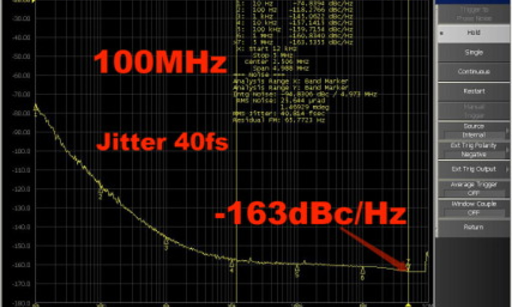
XtalTQ VCXO 100 MHz: 40 fs jitter
XtalTQ VCXO 122.88 MHz: 31 fs jitter
In practical clocking architectures, jitter performance at the tens-of-femtoseconds level can significantly improve converter performance, reduce phase noise contribution in RF synthesizers, and increase timing margin in high-speed digital designs—especially when the clock sits at the root of the distribution tree.
Conclusion: Jitter Is a System-Level Performance Limit
Oscillator jitter may look like a single-line datasheet number, but it acts like a performance ceiling across an entire electronic system. It affects sampling accuracy, data integrity, RF spectral purity, and synchronization across subsystems. If you design communication equipment, precision instrumentation, or any high-speed digital product, selecting a low-jitter oscillator is one of the most effective upgrades you can make.
If you share your target frequency, interface type (LVDS/CMOS/HCSL), and application (ADC clocking, RF PLL, networking, etc.), I can suggest the most relevant jitter and phase-noise specs to prioritize—and how to compare clock sources correctly across different datasheets.


You must be logged in to post a comment.